DBY Electric Diaphragm Pump (DBY Series)
Chemical, Magnetic & Diaphragm Pumps•DBY
- Flow Range
- 0.5 ~ 20 m³/h
- Pressure Range
- 0.3 ~ 0.5 MPa
- Motor Power
- 0.55 ~ 7.5 kW
- Model
- DBY-10 → DBY-100
- Customs HS Code
- 8413.50.90
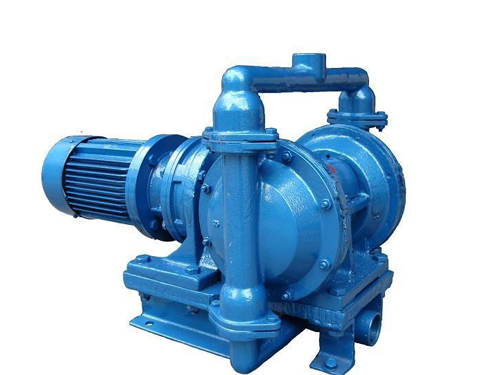
Hydraulic Principle & Internal Construction
The DBY series electric motor-driven mechanical diaphragm pump replaces pneumatic power with a high-efficiency cycloidal or helical gear reducer. Driving opposed flexible diaphragms via a reciprocating crank mechanism, it provides predictable, continuous positive displacement transfer without requiring compressed air infrastructure.
Model-by-Model Technical Specifications
| Model | Inlet | Outlet | Flow (m³/h) | Pressure (MPa) | Speed (rpm) | Motor (kW) |
|---|---|---|---|---|---|---|
| DBY-10 | DN25 | DN25 | 0.5 | 0.3 | 46 | 0.55 |
| DBY-15 | DN25 | DN25 | 1 | 0.3 | 46 | 0.75 |
| DBY-25 | DN32 | DN32 | 3.5 | 0.4 | 52 | 1.5 |
| DBY-40 | DN40 | DN40 | 6 | 0.4 | 55 | 2.2 |
| DBY-50 | DN50 | DN50 | 10 | 0.5 | 58 | 4 |
| DBY-65 | DN65 | DN65 | 15 | 0.5 | 58 | 5.5 |
| DBY-80 | DN80 | DN80 | 18 | 0.5 | 60 | 7.5 |
| DBY-100 | DN100 | DN100 | 20 | 0.5 | 60 | 7.5 |
Selection guidance: match your duty point to the closest model below, then confirm with our engineers. Values are rated operating points at the listed speed.
Need Complete Engineering Dimensions & Curves?
Download the official DBY series 1-page technical datasheet covering all 8 model configurations.
Media Compatibility & Viscosity / Temperature Guide
| Medium | Max Viscosity (cSt) | Application Note |
|---|---|---|
| Electroplating Effluents / Textile Dyeing Wastewater | 20,000 | Particulate Tolerant |
| High-Viscosity Resins & Industrial Adhesives | 50,000 | Electric Drive for Sites Without Compressed Air |
| Spent Chemical Acid Wastes | 5,000 | Filter Press Feed Duty |
| Waterborne Architectural Coatings with Sand Fillers | 30,000 | Abrasion & Particle Resistant |
International Benchmark & Interchange Guide
International Benchmarks
- Wilden electric diaphragm pumps
- DEPAMU / Flux electric diaphragm pumps
Interchange Note
Electric motor mechanical diaphragm pump. Replaces pneumatic AODD pumps where compressed air is unavailable or electric metering drive is preferred.
Materials & Shaft Seal Selection Guide
For DBY electric diaphragm pumps, select gray or ductile iron casings for general wastewater. Use 304 stainless steel for media contact to resist corrosion, or 316L for high-temperature/corrosive environments. Packing seals suit particulate media with periodic gland adjustment; mechanical seals require clean fluids and flushing systems. Choose diaphragms (NBR, FKM, PTFE) based on chemical compatibility and temperature limits.
- Casing & Housing Materials
- HT200 Gray Cast Iron (GG20)Aluminum Alloy304 / 316 Stainless Steel
- Rotor / Gear / Screw Elements
- Crankshaft Connecting-Rod Drive (No Rotating Shaft Seal)
- Diaphragm Materials
- Neoprene Rubber DiaphragmPTFE (Teflon) DiaphragmFKM Fluoroelastomer Diaphragm
- Shaft Sealing Options
- Bolted Clamped Heavy-Duty Diaphragm Static Seal
Engineering FAQ
To prevent cavitation on the DBY pump, ensure the suction pipe diameter matches or exceeds the inlet port size. Install at least 5-10 straight pipe diameters before the inlet to stabilize flow and avoid elbows or valves directly upstream. Maintain a positive NPSHa margin exceeding the pump's NPSHr by at least 10%.
📐 Engineering Selection Methodology
Correct pump selection starts from the fluid, not the pump. Confirm the medium name and actual viscosity at working temperature, the required flow and differential pressure or head, suction conditions (flooded or lift), and whether the fluid crystallizes, shears, contains particles or gas. Positive displacement pumps must always be protected by a relief valve or pressure bypass on the discharge line, and must never be started against a closed valve unless a bypass is fitted. For viscous duties, derate rotational speed to preserve volumetric efficiency; for crystallizing or high-freezing-point media, specify jacketed casings with steam or thermal-oil heating. Our engineers verify each enquiry against these rules before quoting.
🏭 Manufacturing & Quality Control
Castings are produced in our own foundry cluster with material certificates for each heat number. Gear profiles, screw threads and rotor lobes are hobbed, ground and wire-cut to tolerance, then assembled with matched bearing sets. Before dispatch every pump passes casing hydrostatic pressure testing, a run-in test at rated speed on an oil bench, and relief valve cracking-pressure verification; test records are archived against the pump serial number and can be supplied with the shipment.
📦 Export Packaging & Delivery
Pumps are preserved with anti-rust coating, flanges blanked, and packed in export-grade plywood cases with steel strapping for sea freight. Document packs include operating manual, performance test record, packing list and material certificates on request. Standard models ship from stock; engineered configurations typically require 15-35 days depending on casing material and seal options. Spare rotor sets, seal kits and relief valve assemblies can be quoted together with the base pump.
Typical Applications & Industry Use Cases
The media compatibility table above maps directly to real industry duties. In lubrication circuits, size the pump for continuous duty at 70-80% of rated flow to leave margin for viscosity drift as oil warms up. In chemical transfer, confirm the medium's specific gravity and whether it is shear-sensitive before fixing rotational speed. In food and sanitary service, schedule CIP cycles around the product changeover plan and verify elastomer compliance with the relevant food-contact regulation in your market. In hot oil and asphalt service, always pre-heat the casing to the medium temperature before start-up so internal clearances are at operating dimension - a cold start against solidified product is the single most common cause of gear pump failures reported from the field.
Commissioning & Maintenance Guidance
Before first start: verify rotation direction, fill the casing with medium, open the discharge bypass, and jog the motor to confirm free rotation. Check the relief valve setting against the system design pressure and lock the adjuster. During the first hour, record suction and discharge pressures, medium temperature, and motor current - deviations from the quotation duty point usually indicate suction restriction or an over-throttled discharge line. Routine maintenance intervals: inspect the shaft seal weekly during the first month, then monthly; check coupling alignment after any pipe work; drain and inspect the bearing housing annually. Keep a log of running hours so rotors, bearings and seals can be replaced on condition rather than after failure.
Troubleshooting Quick Reference
No delivery or loss of prime: check suction line for air ingress, verify foot valve and strainer are submerged and clean, and confirm the casing is primed for pumps without self-priming capability. Flow below nameplate: verify actual rotational speed against the data sheet, confirm medium viscosity is within the rated band, and inspect internal clearances for wear if the pump has long service hours. Abnormal noise or vibration: usually coupling misalignment, cavitation from excessive suction lift, or foreign matter in the pumping chamber. Seal leakage: confirm flush plan and seal face condition; never run a mechanical seal dry. Motor overload: check for over-viscous medium at start-up temperature and confirm the relief valve is not set above the motor's capability. For anything beyond these basics, send us the serial number and symptom - our engineers will respond with a diagnosis.
📋 Standards, Testing & Documentation
Gear pumps in this catalog are designed and acceptance-tested with reference to JB/T 6434 (external gear pumps), three-screw pumps to GB/T 10886, centrifugal chemical pumps to ISO 2858, and sealless or screw pumps to the relevant API 676 guidance, with mechanical seals supplied to API 682 configurations on request. Sanitary models are manufactured with surface finishes suitable for FDA / 3A style hygienic duties. Each shipment can include: performance test record against the quoted duty point, hydrostatic test certificate, material certificates for pressure-retaining parts, operating and maintenance manual, and a dimensional drawing with flange table. Tell us which standards your project specification cites and we will align the documentation pack accordingly.
🔧 Spare Parts & After-Sales Support
Every pump model page doubles as a spare-parts reference: rotor and gear sets, bearing and thrust assemblies, complete seal cartridges, relief valve kits and jacket gasket sets are manufactured in-house to the same drawings as the original build - so spares ordered years later still match. Recommended commissioning spares are one seal set and one gasket set per pump; for critical continuous-duty installations we recommend a full rotor set held on site. When ordering spares, quote the pump serial number and nameplate data so the correct material and clearance class is supplied. Technical support in English is available by email during China business hours, with video call diagnostics available for installation and commissioning issues.
ℹ️ Technical data on this page is sourced from the manufacturer's engineering database and applicable standards (JB/T 6434, GB/T 10886, ISO 2858, API 676). Final selection must be confirmed by our engineers against your actual duty conditions.
Direct 1-Click Engineering Contact
Skip the form — connect directly with our application engineers via WhatsApp or Email for instant technical drawings, sizing, and pricing.
Related Pump Models
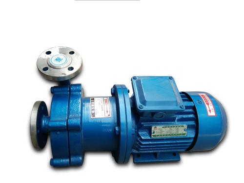
CQB Magnetic Drive Centrifugal Pump
Chemical, Magnetic & Diaphragm Pumps • CQB
- models
- 10 (CQB-32-20-125 → CQB-100-65-315)
- Flow Range
- 3.2 ~ 100 m³/h
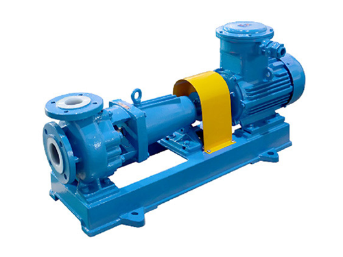
IHF Fluoroplastic-Lined Chemical Centrifugal Pump
Chemical, Magnetic & Diaphragm Pumps • IHF
- models
- 9 (IHF-32-25-125 → IHF-150-125-250)
- Flow Range
- 3.5 ~ 200 m³/h
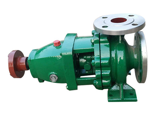
IH Stainless Steel Chemical Centrifugal Pump
Chemical, Magnetic & Diaphragm Pumps • IH
- models
- 6 (IH-50-32-125 → IH-150-125-315)
- Flow Range
- 6.3 ~ 200 m³/h
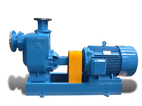
CYZ Self-Priming Centrifugal Oil Pump
Chemical, Magnetic & Diaphragm Pumps • CYZ
- models
- 10 (CYZ-20 → CYZ-200)
- Flow Range
- 3.2 ~ 600 m³/h